Hollywood, California +1 (323) 466-5444 www.pipo.cc
SPECIAL PRODUCTS
PT-1 – RELAY TIMING DEVICE BOARD
Features:
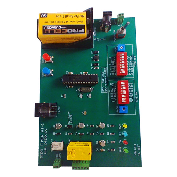
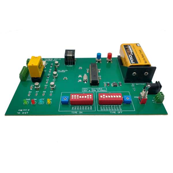
The PT-1 Relay Timing Device Board generates a programmable binary output signal (ON/OFF), with customizable durations for both the ON and OFF states. The output is continuous and repetitive, starting with the press of the ‘Start’ button and stopping when the ‘Stop’ button is pressed.
The PT-1 offers three output options: two relay outputs and one open-collector transistor output. The open-collector output is especially useful for shorter times, where relay response times might be insufficient.
To program the ON and OFF times, we can use either DIP switches or potentiometers, allowing precise adjustments. When using DIP switches, times can be set from 10 milliseconds to 5 minutes. If using potentiometers, times can be continuously adjusted between 100 milliseconds and 10 seconds.
The PT-1 Pipo Timer Time Table below details the DIP switch settings for programming ON and OFF times. If DIP switches ON7 and ON8 are set to closed positions, time programming will be handled by the respective ON and OFF potentiometers.
The board is also equipped with LEDs for output indication, along with a connector for programming the microcontroller’s FLASH memory.
Specifications:
• Power Supply: 10-14 VDC or 9V Battery
• Power Consumption: Less than 250mA
• User Interface: DIP switches, potentiometers, Start/Stop buttons, and indicator LEDs.
• Programming Range with DIP Switches: Adjustable from 10mS to 5min.
• Programming Range with Potentiometers: Continuously adjustable from 100mS to 10sec.
• Output 1: Relay (COMMON, Normally Open – NO).
• Output 2: Relay (COMMON, Normally Open – NO, Normally Closed – NC).
• Output 3: Open-Collector Transistor (20V, 300mA).
• Dimensions: 6.0″W, 4.0″D, 1.5″H.
PT-1 PIPO TIMER TIME TABLE
PT-1 PIPO TIMER PCB PLACEMENT & 3D-VIEW
PT-1 PIPO TIMER ELECTRICAL SCHEMATIC
PETB-01 – PIPO ENCODERS TEST BOARD
Features:
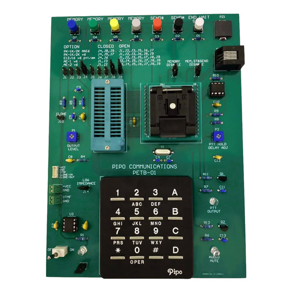
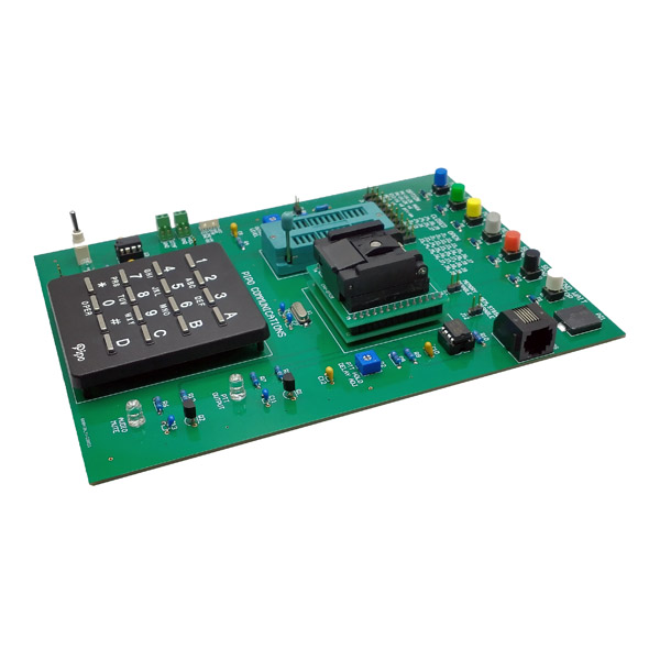
The PETB-01 – Pipo Encoders Test Board was designed to test the firmware developed for all DTMF encoders version 6.5 or higher from Pipo Communications.
In addition to testing the firmware, the PETB-01 also programs and tests the chips used in the encoders. These chips can come in either DIP-28 or QFN28 packages, and the board includes sockets for both types.
The firmware and hardware for each decoder model are selected using jumpers, with a selection table printed on the PETB-01 PCB.
The board also includes a connector for programming the flash memory of microcontrollers. This connector is also used to program the DTMF memories of various products through an USB cable connected to a PC, using the “Pipo Communications DTMF Encoder Programmer – Version 6.5” software.
Additionally, the board includes all the necessary components to simulate the hardware of all Pipo DTMF encoder models version 6.5, such as buttons, a keyboard, a piezo buzzer, EEPROM memory, and more.
Specifications:
• Power Supply: 6-26 VDC.
• Power Consumption: Less than 200mA.
• User Interface: Buttons and 16-key keypad.
• DTMF Output: High and low impedance, selectable via jumper.
• PTT Output and Audio Mute: Indicated by LEDs.
• Microcontroller Packages: DIP-28 and QFN28.
• Dimensions: 5.51″W, 7.48″D, 1.50″H.
PETB-01 TEST BOARD PCB PLACEMENT & 3D-VIEW
PETB-01 TEST BOARD ELECTRICAL SCHEMATIC
PETB-01 TEST BOARD USB PROGRAMMING CABLE